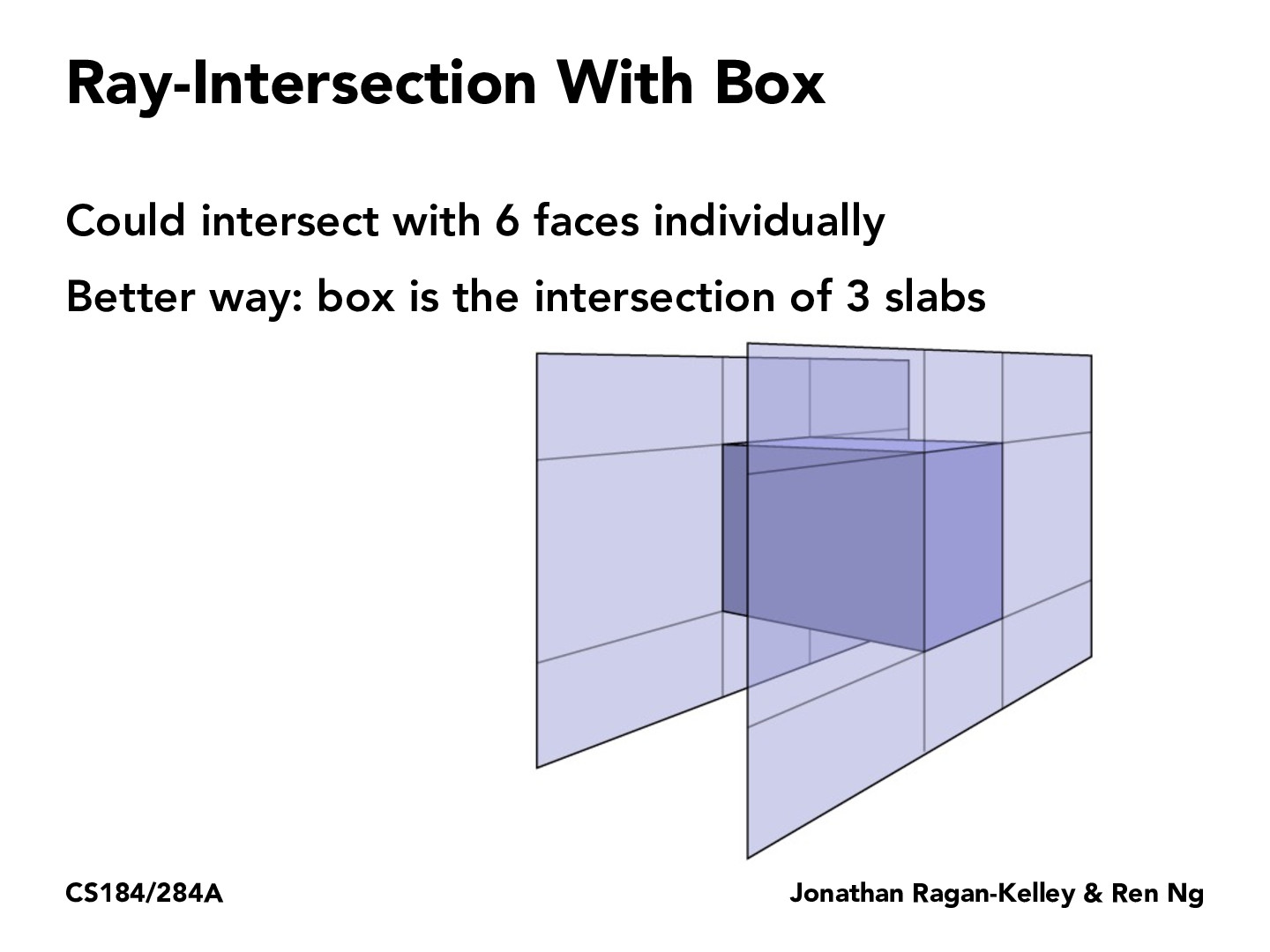
From the diagram in lecture, it seemed to still be using 6 planes extending from the faces to check intersections with the box. Are we pairing up opposite planes out of those 6 to bound 3 slab cross sections of the box?
woojinko
From the diagram in lecture, it seemed to still be using 6 planes extending from the faces to check intersections with the box. Are we pairing up opposite planes out of those 6 to bound 3 slab cross sections of the box?
michaeltu1
Basically yes. To provide potential intuition as to why, instead of thinking of intersecting 3 slabs to form one 3D-slab that provides a bounding box around the object, first consider using 3 orthogonal vectors to intersect the object. Assuming for each of those vectors/rays we'll be able to get the minimum and maximum values of t for which the ray o + td intersects the object. The minimum and maximum values we get from each orthogonal vector would could then in a sense form a slab in from t_min to t_max where the opposite planes that bound the slabs are orthogonal to the intersecting ray, and the points at which the ray intersects each of the orthogonal planes are at either t_min or t_max. Now that we have 3 slabs, we would take the intersection (probably making use of the t_min and t_max values) to form the 3D slab intersection depicted. I don't know if the rays have to be orthogonal, I just mentioned it as a way to better understand what is happening
From the diagram in lecture, it seemed to still be using 6 planes extending from the faces to check intersections with the box. Are we pairing up opposite planes out of those 6 to bound 3 slab cross sections of the box?
From the diagram in lecture, it seemed to still be using 6 planes extending from the faces to check intersections with the box. Are we pairing up opposite planes out of those 6 to bound 3 slab cross sections of the box?
Basically yes. To provide potential intuition as to why, instead of thinking of intersecting 3 slabs to form one 3D-slab that provides a bounding box around the object, first consider using 3 orthogonal vectors to intersect the object. Assuming for each of those vectors/rays we'll be able to get the minimum and maximum values of
tfor which the rayo + tdintersects the object. The minimum and maximum values we get from each orthogonal vector would could then in a sense form a slab in fromt_mintot_maxwhere the opposite planes that bound the slabs are orthogonal to the intersecting ray, and the points at which the ray intersects each of the orthogonal planes are at eithert_minort_max. Now that we have 3 slabs, we would take the intersection (probably making use of thet_minandt_maxvalues) to form the 3D slab intersection depicted. I don't know if the rays have to be orthogonal, I just mentioned it as a way to better understand what is happening