In projects 3-1 and 3-2, we were doing all of our raytracing computation on CPU. You've likely felt the effects of this already, waiting minutes to render a single frame with any realistic lighting, even with threading. For real-time and interactive applications, which often have framerates of 60 fps (that's 60 frames per second), this is just impossibly slow. In this part, you will get a glimpse of how things may be accelerated by writing a few basic GLSL shader programs. Shaders are isolated programs that run in parallel on GPU, executing sections of the graphics pipeline, taking in an input, and outputing a single 4 dimensional vector. Recall the brief overview of shader programs given in lecture.
First let's get acquainted with GLSL, a C like language in which we will write our shaders. This is a great highlevel overview of the basic constructs of the language. Take a minute to look through the definitions. TLDR:
- A GLSL shader can have functions just like C
- An attribute is an input to a vertex shader (position, normal, uv coordinates)
- A uniform is shared by all instances of the running program (light position, textures, transform matrices)
- A varying is typically written into by the vertex shader for use in the fragment shader (transformed positions, normals, uv coordinates)
- GLSL has built-in types and operations that make vector math simpler like
vec3,vec4,mat4,dot,length
We will be dealing with two basic OpenGL shader types:
- vertex shaders: These shaders generally apply transforms to vertices, modifying their geometric properties like position and normal vectors, writing the final position of the vertex to
gl_Positionin addition to writing varyings for use in the fragment shader. - fragment shaders: After rasterization, we end up with fragments, which these shaders process. These shaders generally take in geometric attributes of the fragment calculated by the vertex shader to compute and write a color into
out_color.
To create a shader program, we compile and link a vertex and fragment shader, the output of the vertex shader becomes the input of the fragment shader.
NB: Because we didn't want to make a high-end GPU part of CS 184's required hardware, our shaders only use up to OpenGL 3.3 features. Shaders post OpenGL 3.3 have some much nicer features and syntax, but operate on entirely the same principles. If you're interseted, learnopengl.com is an excellent guide for modern openGL programming.
Getting Started
The skeleton will automatically search for and load shader programs contained in the shaders directory. A simple shader program is made of two parts:
- A
.vertfile, which specifies a vertex shader. The vertex shader is responsible for reading and writing all per-vertex values. These per-vertex values are then interpolated via barycentric coordinates across the polygon's face. - A
.fragfile, which specifies a fragment shader. The fragment shader is responsible for writing all per-pixel* values. It takes as input the interpolated per-vertex values from the vertex shader and outputs the final color of that pixel.
The skeleton will scan the shaders directory for <NAME>.frag shaders, and link it to the corresponding <NAME>.vert, defaulting to Default.vert if none exists. (Shader-based final projects might want to take advantage of this behavior!)
When writing your shaders, be sure to pay extra attention to the types you are using. GLSL 1.0 will not automatically promote ints to floats or demote floats to ints. Function calls must match their declared types exactly as well, so something like max(2, 3.0) will cause the shader to fail compilation. In addition, the built ins gl_Position and gl_FragColor are both of type vec4, the first expecting homogenous coordinates and the second expecting an rgba vector. Many of our calculations will be done using vec3's, so don't forget to convert back to a vec4 (an easy way is simply use vec4(my_vec_3, w_coordinate)).
*Note: technically, a fragment shader writes "per-fragment" not "per-pixel" values. An OpenGL fragment is much closer to our notion of a sample than a pixel. Recall that in super-sampling anti-aliasing, a single pixel might represent the averaged color of multiple individual sample points. Additionally, we might take samples that are overwritten or occluded by those of other polygons. Nevertheless, for most purposes, we can think of a fragment as equivalent to a pixel.
Task 1: Diffuse Shading
Relevant Files:
shaders/Default.vertshaders/Diffuse.frag
In project 3-1, you saw how diffuse objects appear under light in the world. Let's try to recreate this in a shader program. In Default.vert, we can see an example of a simple vertex shader. It takes in as input the model-space attributes of in_position and in_normal, both of type vec4, in addition to the uniforms u_model, u_view_projection, which are the matrices used to transform a point from model space into world space, and from world space to view space to screen space respectively. We output two values for use in the fragment shader: v_position and v_normal.
Taking a look at the main function, we see that the world space position and normal vector are written into the corresponding varyings v_position and v_normal and the screen space position is written into gl_Position.
Recall the formula for diffuse lighting from the lecture:
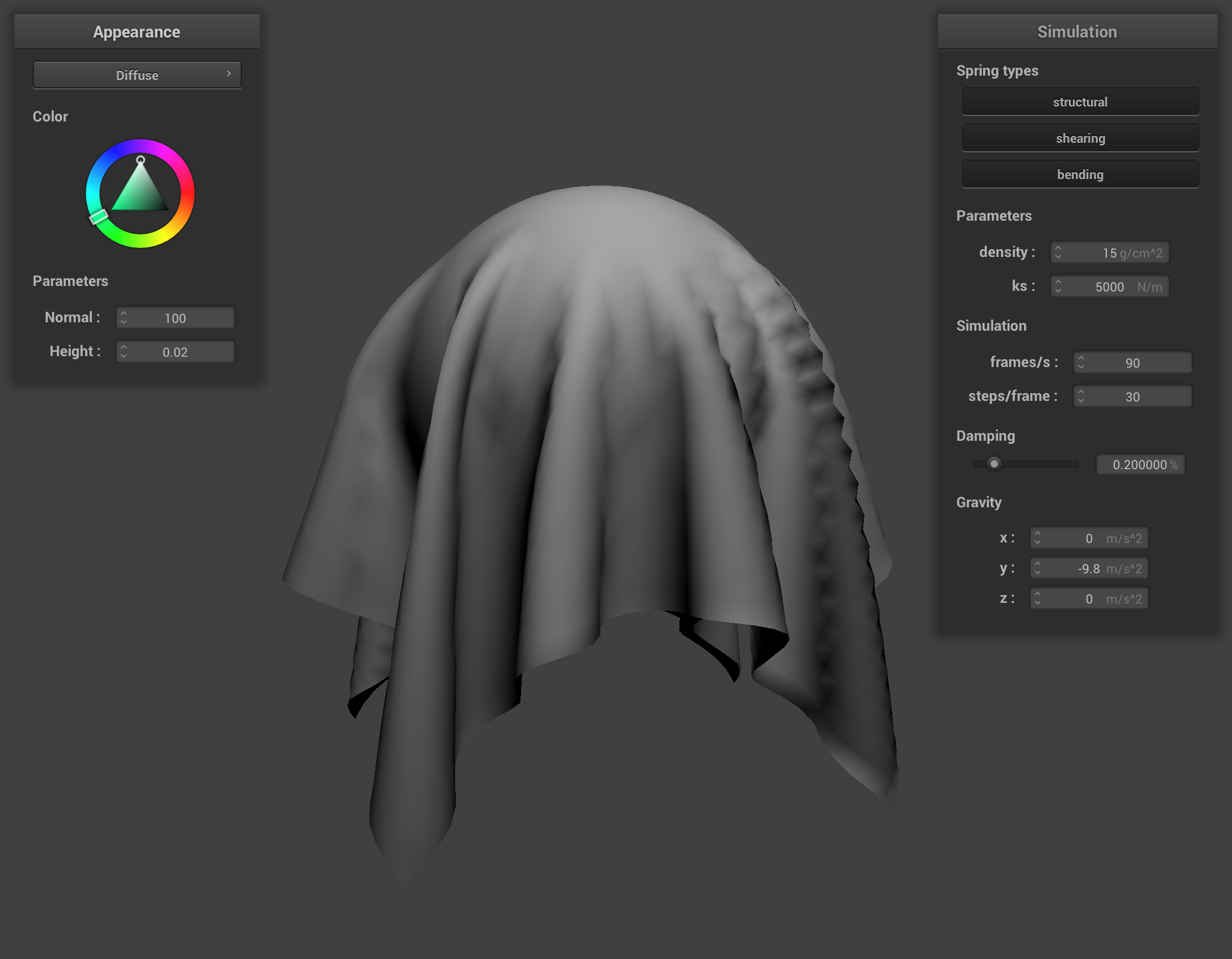
Now in Diffuse.frag, output into out_color the color of the fragment. The light intensity and position are provided as uniforms to the fragment shader. You may choose your own diffuse coefficient vector (you probably just want 1).
After completing this part, you should be able to render the cloth like below:
Task 2: Blinn-Phong Shading
Relevant Files:
shaders/Default.vertshaders/Phong.frag
Now let's create a shader capable of performing Blinn-Phong shading. Recall the equation for Blinn-Phong shading from lecture:
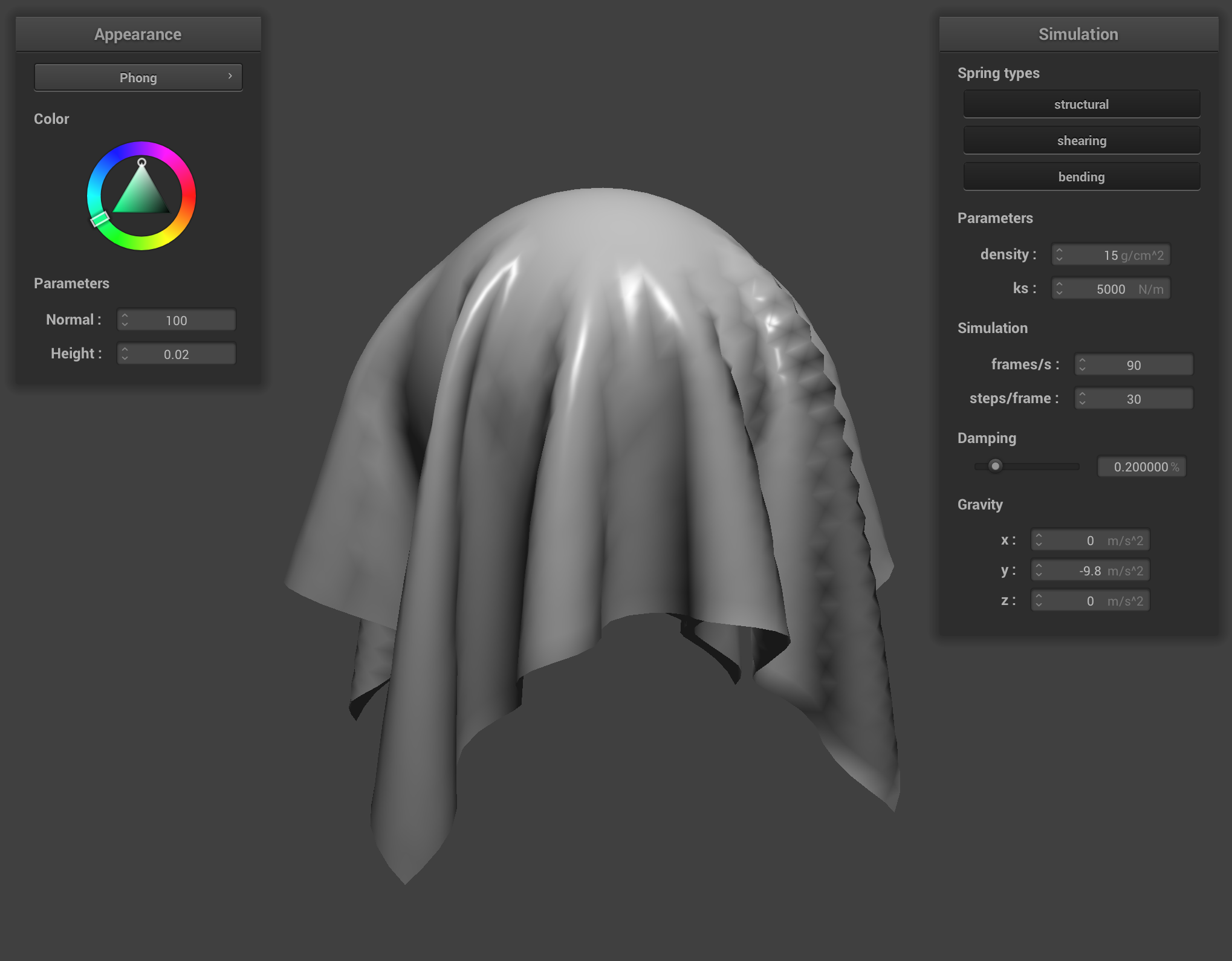
Notice we add both an ambient light component and specular reflection component to the diffuse lighting from the previous part to calculate the output light. As before, the light intensity and position are passed as uniforms to the shader. Complete the main function in Phong.frag to implement the Blinn-Phong shading model. You may decide on to suite your tastes. After completion, you should be able to see some nice specular lighting effects:
Task 3: Texture Mapping
Relevant Files:
shaders/Default.vertshaders/Texture.frag
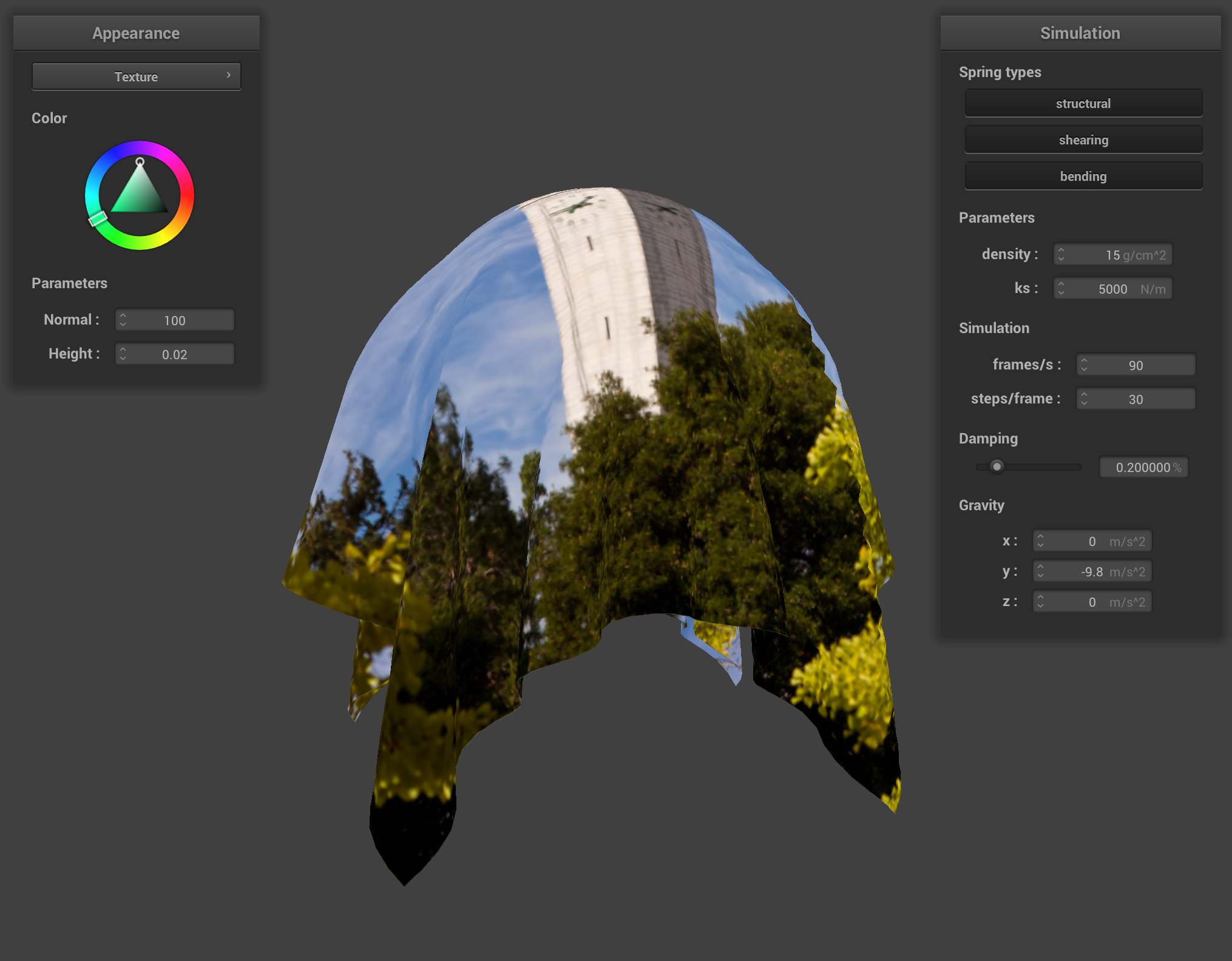
Looking at Default.vert, we can notice that this shader also takes in a in_uv coordinate associated with the instance's vertex and writes it into v_uv for use in the fragment shader.
We can sample from the u_texture_1 uniform using the built-in function texture(sampler2D tex, vec2 uv), which samples from a texture tex at the texture space coordinate uv. In Texture.frag, complete the shader so that the sampled spectrum is output as the fragment's color.
Task 4: Displacement and Bump Mapping
Relevant Files:
shaders/Bump.fragshaders/Displacement.vertshaders/Displacement.frag
We can use textures for more than just determining the color on a mesh. With displacement and bump mapping, we can encode a height map in a texture to be processed and applied by a shader program. NOTE: You don't have to generate exactly the same results as we have in our reference images, just make sure the results are plausible.
4.1: Bump Mapping
In bump mapping, we modify the normal vectors of an object so that the fragment shader gives the illusion of detail (such as bumps) on an object. How can we calculate the new normals given the height map?
To make our calculations easier, we can work in object space, where all normal vectors initially point directly out of the local vertex and have a z-coordinate of 1. Given a vector in object space, we can transform it into back into model space by multiplying by the tangent-bitangent-normal (TBN) matrix.
We already know the original model-space normal vector as this is an input to our vertex shader. We can pre-compute the tangent vector from the mesh geometry, and this will also be passed as an attribute to the vertex shader. The bitangent should be orthogonal to both the tangent and normal and can be found using the cross product . We then have:
Because we have access to the entire height map, we can compute the local space normals by looking at how the height changes as we make small changes in or . Let be a function that returns the height encoded by a height map at texture coordinates and and and be the width and height of our texture.
is a height scaling factor and is a normal scaling factor represented in our shader by the u_height_scaling and u_normal_scaling variables. The local space normal is then just . Our displaced model space normal is then .
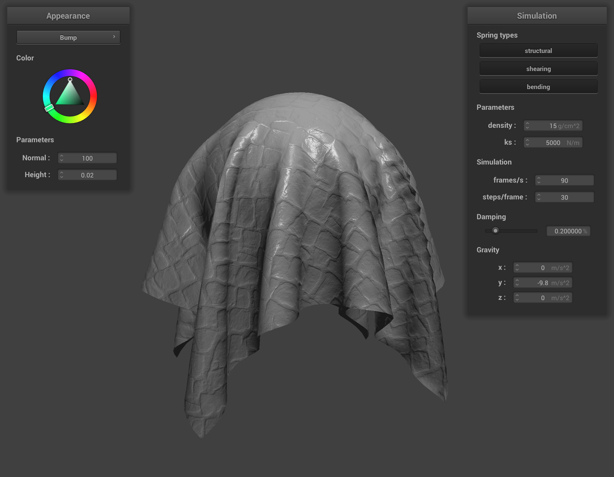
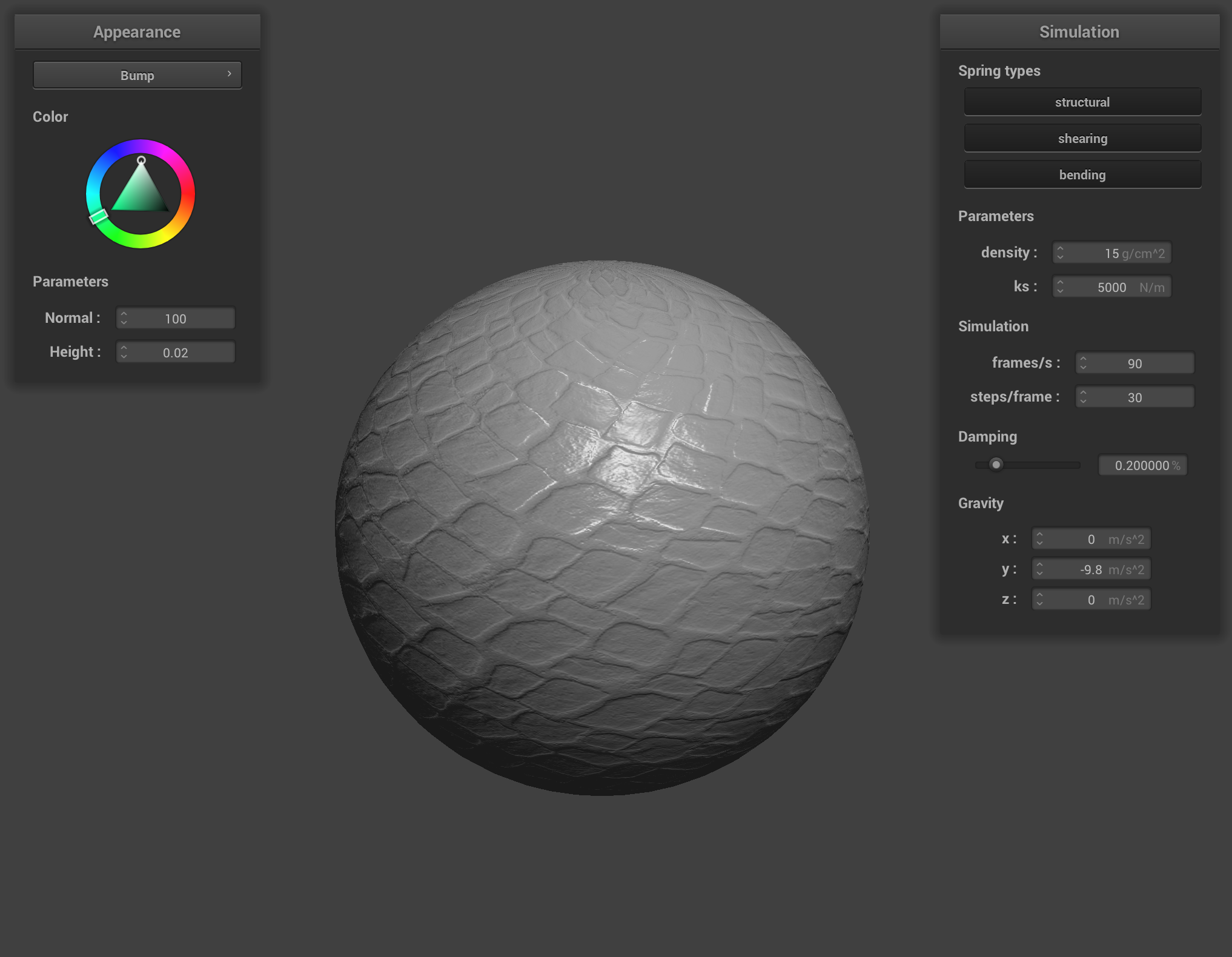
Complete the main function in Bump.frag to calculate the displaced world space normal. The height map is stored in the u_texture_2 texture and the resolution of the texture is stored in vec2 u_texture_2_size. One such you could use would be the r component of the color vector stored in the texture at coordinates . On completion, you should be able to see some realistic lighting effects on the mapped bumps:
4.2: Displacement Mapping
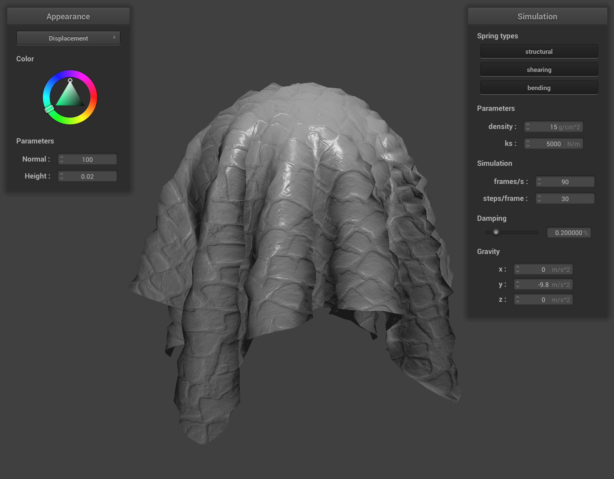
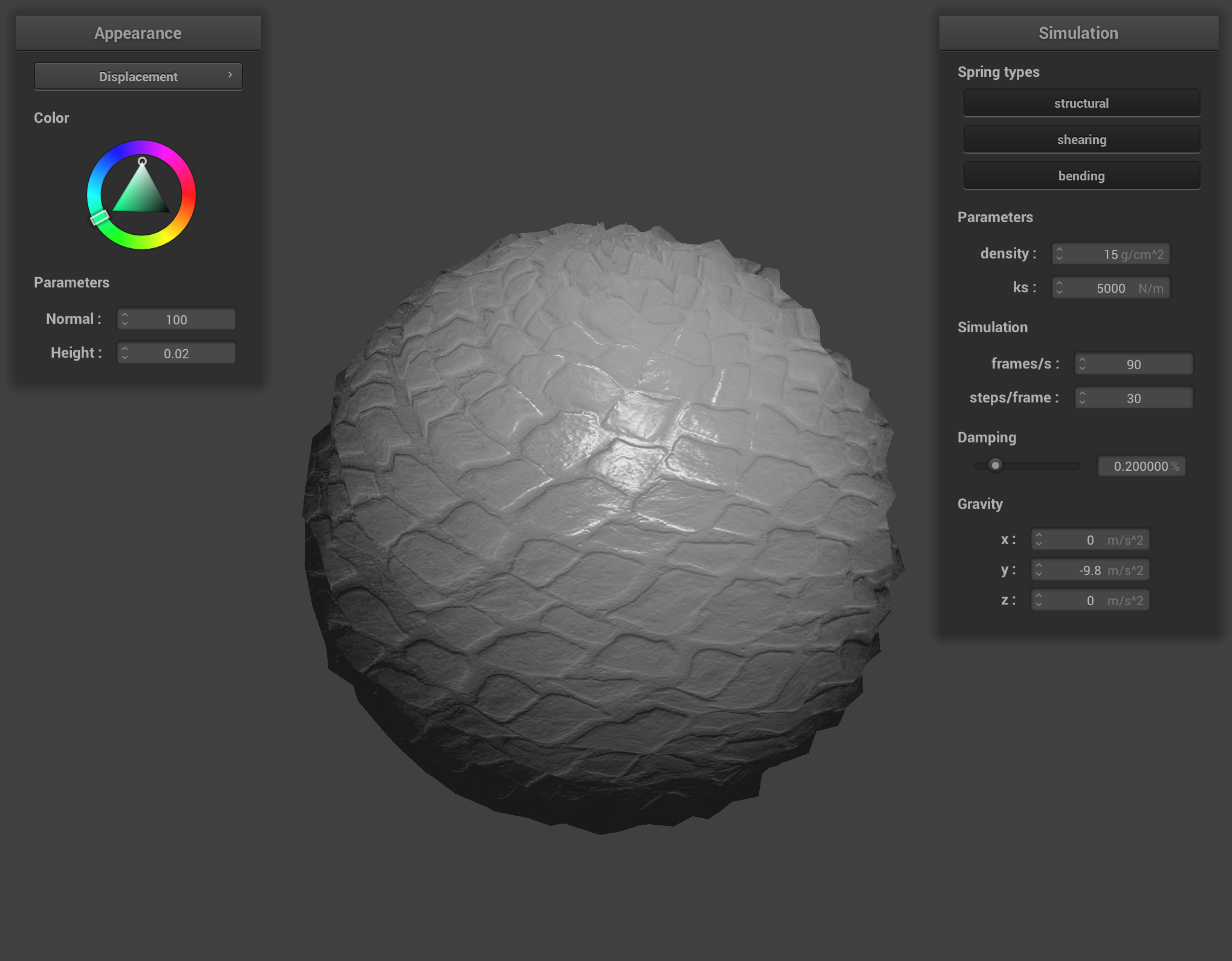
In displacement mapping, we modify the position of vertices to reflect the height map in addition to modifying the normals to be consistent with the new geometry. First, copy your fragment shader from Bump.frag into Displacement.frag. Modify Displacement.vert so that it also displaces the vertex positions in the direction of the original model space vertex normal scaled by the u_height_scaling variable:
On completion, you should be able to notice the change in geometry:
Task 5: Environment-mapped Reflections
Relevant Files:
shaders/Mirror.frag
In the pathtracer project, we saw a simple model for a mirror material. We took the incoming eye-ray, reflected it across the surface normal to get the outgoing direction, and then sampled the environment for that direction's incoming radiance.
Here, we will approximate the incoming radiance sample using an environment map, which is a pre-computed store of the direction-to-radiance mapping we previously calculated explicitly via monte carlo integration. We do this by enclosing our scene inside of an infinitely-large room with the environment's appearance painted on the inside. If this sounds like the environment lights from the previous project, you're right! However, as a part of the approximation, we will sample the environment map without shadow rays (assumes no intersections with other parts of the scene).
Using the camera's position u_cam_pos and the fragment's position v_position, compute the outgoing eye-ray, . Then reflect across the surface normal given in v_normal to get . Finally, sample the environment map u_texture_cubemap for the incoming direction .
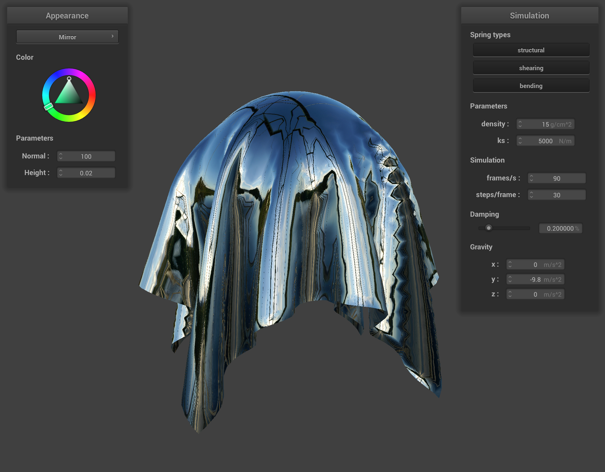
We can sample from the u_texture_cubemap uniform again using the built-in function texture(samplerCube tex, vec3 dir) overload, which samples from a texture tex at looking down the direction dir.
(For the cubemap used above and other great cubemap textures, check out Emil Persson's site.)
Extra Credit Opportunity:
Relevant Files:
shaders/Custom.vertshaders/Custom.frag
Make your own shader or scene! If you need more space to work, you can edit loadObjectsFromFile() in main and add a new object type. It can be as complex as you desire.
Add color controls to a previous shader, add a time uniform to generate procedural scenes, add a new object type or texture and see how your shaders work with them! Try combining together all 5 shader types and see what you can make!